Get the source code and schematics here
While I’ve always been interested in electronics, I mainly got into software because software affords the flexibility to make mistakes. The cost of failure is low and there is room for experimentation without the risk of wrecking anything expensive (most of the time). While this is great, I always get the gnawing feeling that somehow the things I build are less real, or least less understood than building physical objects. At the very least, hacking away on a keyboard is much less romantic than hammering & soldering in a workshop with some high voltage apparatus. So for someone like myself, the appearance of low cost general purpose computers such as the Raspberry Pi has been really exciting. It lowers that cost of failure in electronics and allows a pathway for bringing things I build into the physical world.
The thought of building something that was more than just software has been eating up real estate in the back of my mind for some time now, so I finally decided that I would make my contribution to the Internet of things. As someone who has began dabbling in gardening, and has also had to weather (pardon the pun) high water costs due to Californias drought - I decided to build some sort of intelligent drip irrigation system that would only water when weather conditions required it, saving myself the time of daily watering, and also some water (and $) in the process.
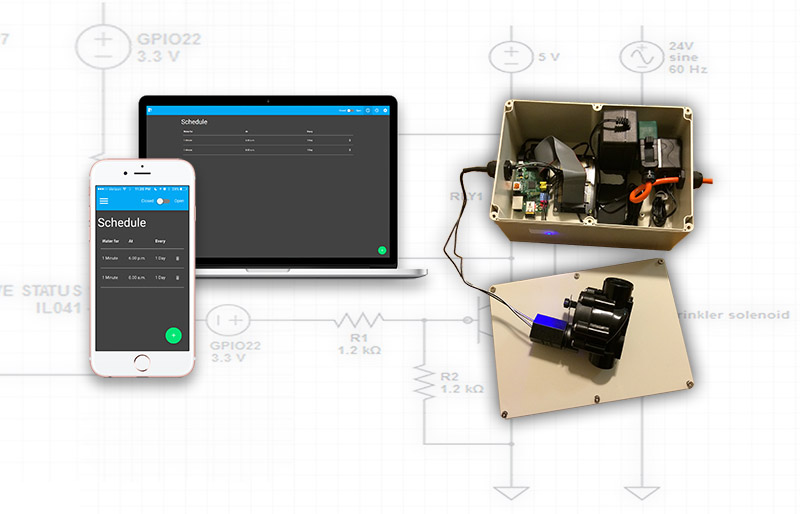
The general design I came up with was to use the Raspberry Pi running a web server, this server would host a web interface and a scheduler and would control a solenoid water valve attached to the Pi. I’d place the completed device in a waterproof enclosure attached to the water supply a set of drip irrigation piping. With this in mind I put together my initial shopping list.
The hardware
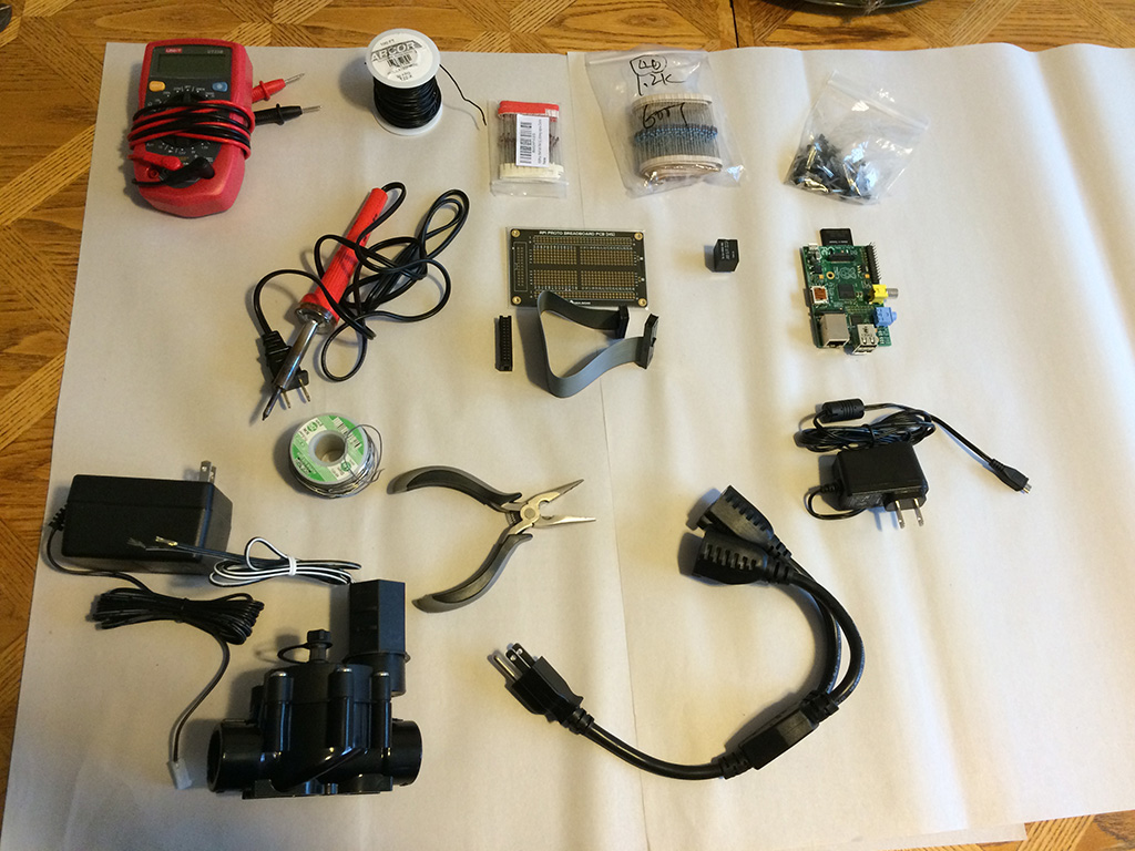
Most of the components
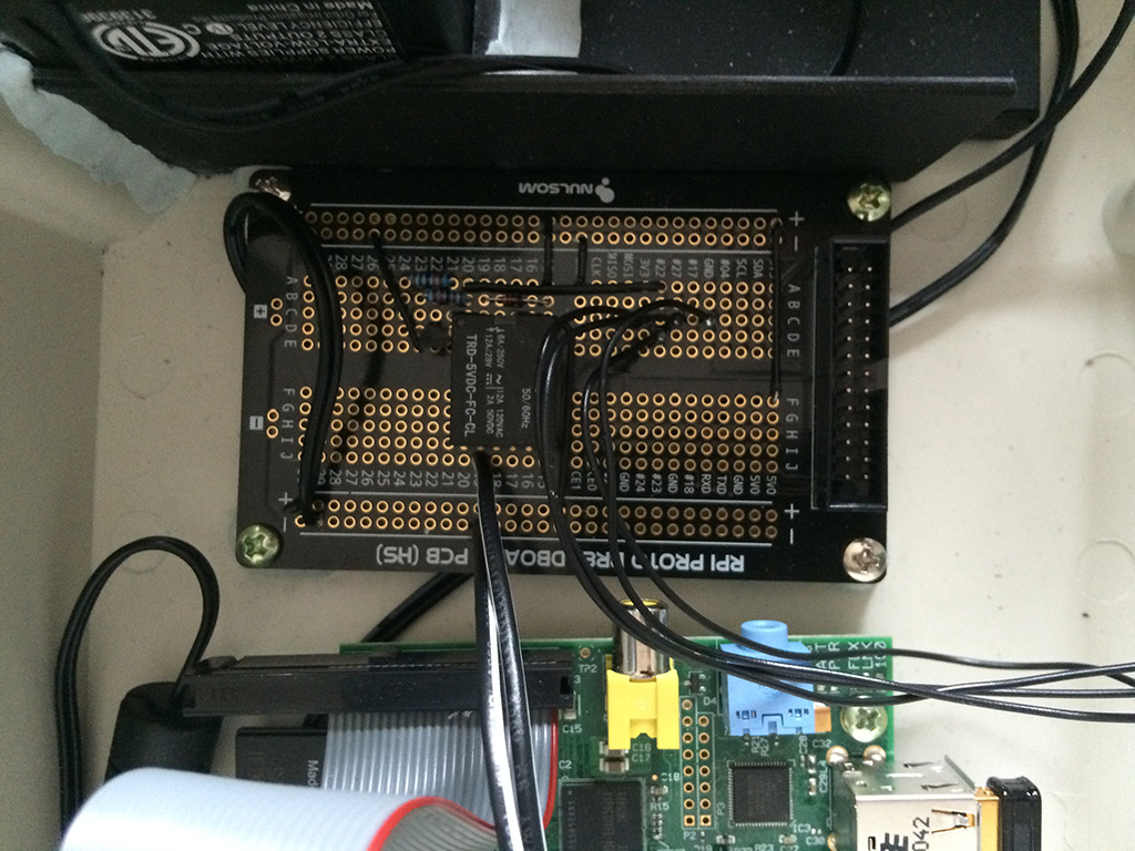
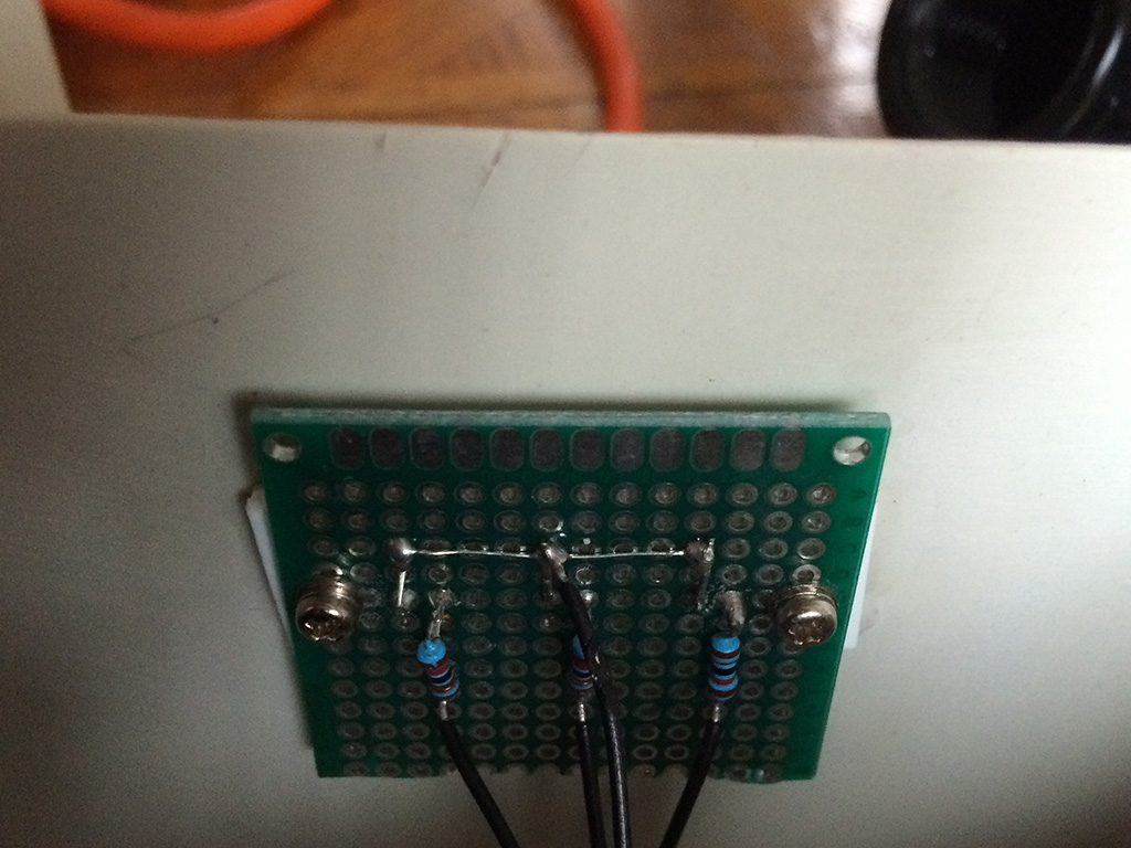
The circuit layed out and soldered onto the protoboard
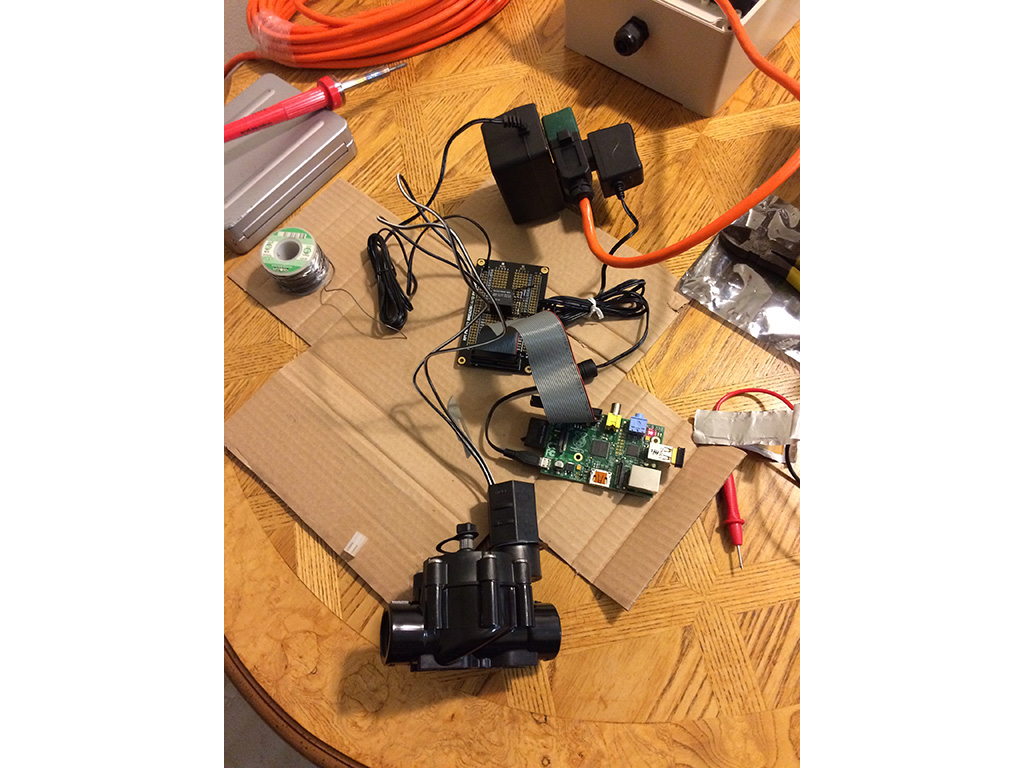
The test rig used to test the solenoid was activating when the software set the GPIO port values
The LED status light assembly
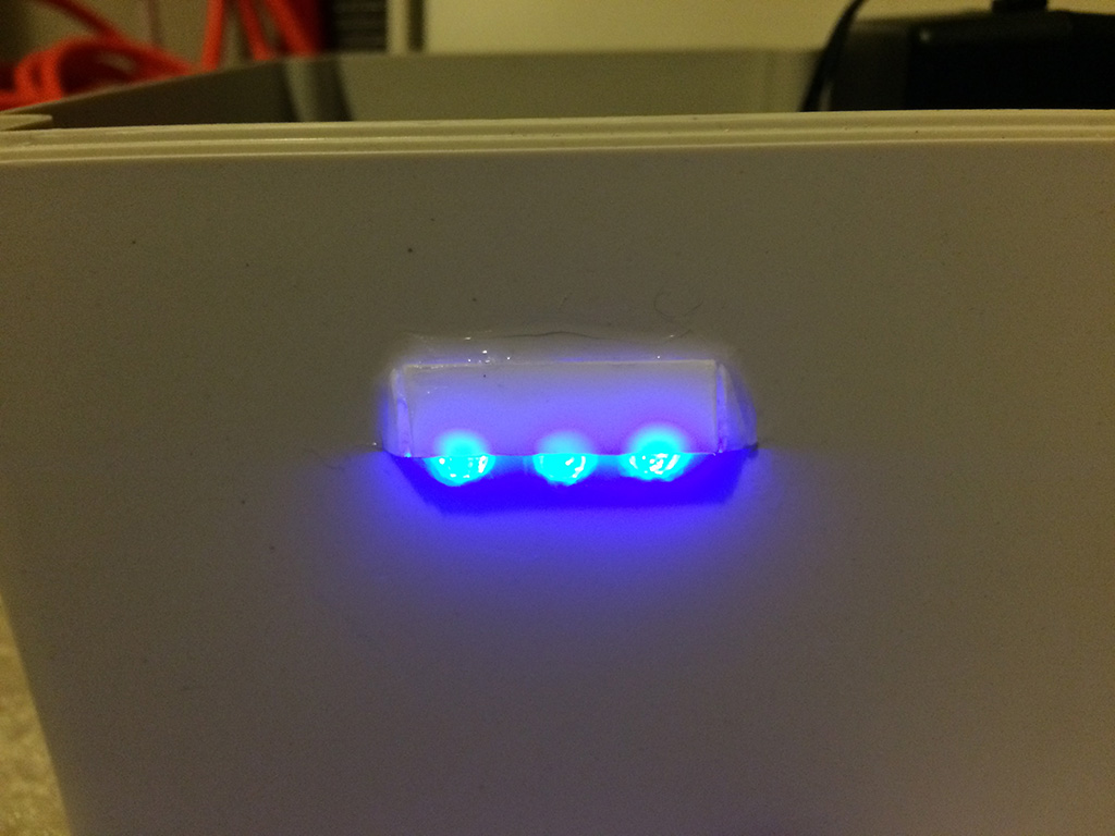
The front side of the LED status assembly
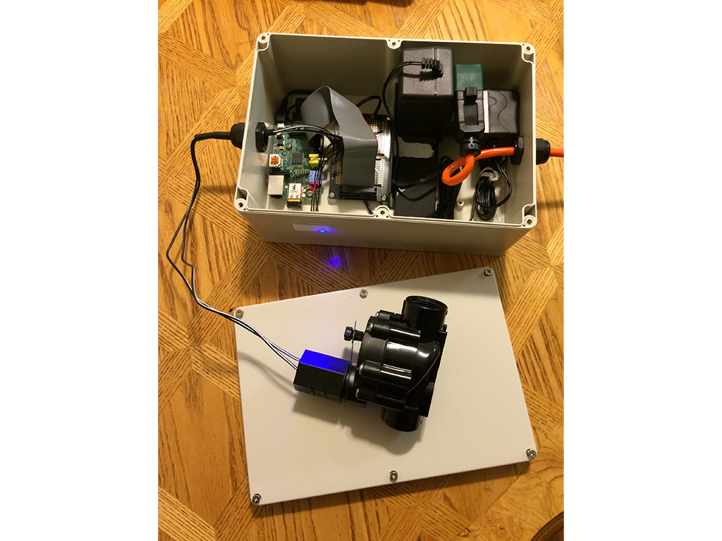
The final assembly layed out in the enclosure
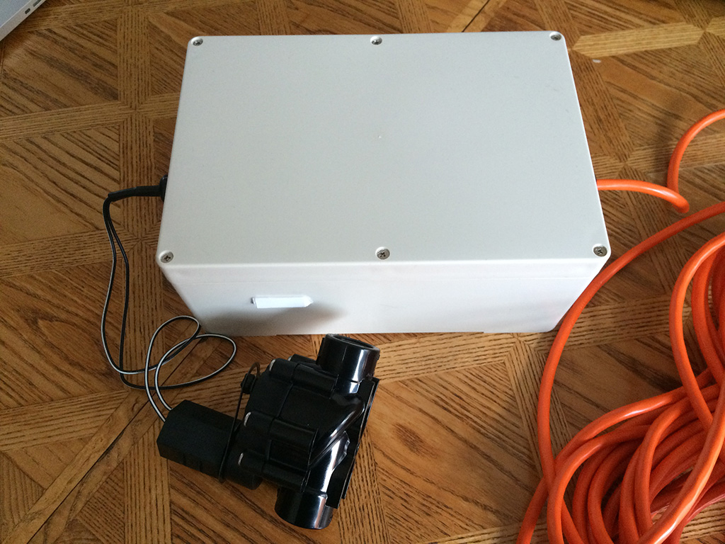
Everything closed up and weather proofed
The components
- 1 Raspberry Pi (Running Raspbian Jessie lite)
- 1 x 32GB SD card
- 1 24V AC Solenoid water valve
- 1 protoboard
- 3 x 3.3V LEDs
- 5 x 1.2 kOhm resistors
- 1 x 2N2222 transistors
- 1 x 1N4148 diode
- 1 x 5V relay
- 1 x 5V DC micro USB power supply
- 1 x 24V AC transformer
- 1 x plastic electronics enclosure
- 1 x outdoor extension cord
- 1 x power splitter
- 1 x USB wifi dongle
Controlling the switch
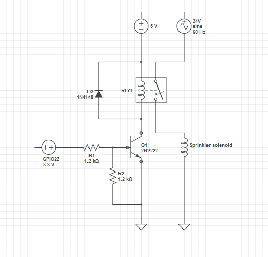
I decided to use a 24V AC relay as it is the most commonly available solenoid valve. This meant that I was going to need to devise some control circuitry as the Raspberry Pi runs at 5.5v and its GPIO ports can only supply 3.3v so I wouldn’t just be able to hook it up directly. The way I did this was to use a relay that would activate when 5v was put across one side, this would be used as a switch to control the 24vac switch. To activate the relay I used a transistor with the base attached to one of the Raspberry Pi’s GPIO ports - the 3.3v is enough to energize the base of the transistor, which would complete the circuit to ground providing the 5v across the relay, letting us switch the solenoid via a single GPIO port being on/off. The circuit diagram for this is shown below.
Status LEDs
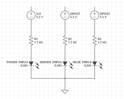
As a last minute addition I noticed that once all the components were sealed away there would be no way of knowing if it was running or what the software was doing, so I decided to add a set of 3 status LED’s. One LED would indicate power, one would indicate that the server software was running, and the 3rd would illuminate when the solenoid switch was activated. The circuit diagram for this is shown below.
Initial testing
To control the GPIO ports I used the onoff library which makes it simple to set the state of any of the Raspberry Pi’s GPIO ports. I wrote the following test script to test my initial circuit. When running it toggles GPIO port 22 once every second, which meant that once I attached the circuit above, I should hear the relay click on and off once per second like a metronome.
import onoff from 'onoff';

output = new onoff.Gpio(22,'out');

let value = 0;
setInterval(() => {
  value = value ? 0 : 1;
  output.writeSync(value);
},1000);

process.on('SIGINT',() => output.unexport());
Initially nothing worked, I found after some multimeter testing that I had soldered the pin header on backwards so none of the outputs were going where I expected them to. After filing off the notch key on the parallel cable connecting the Pi to the protoboard and plugging it in the other way, everything worked! The relay clicked happily every time I ran my test script. After determining that everything was working, and with the help of some epoxy cement, superglue, silicon sealant, and some old parts from a PC case I got everything attached securely into the plastic enclosure and added waterproof cable glands to the entry points for the power and solenoid cables.
The web UI
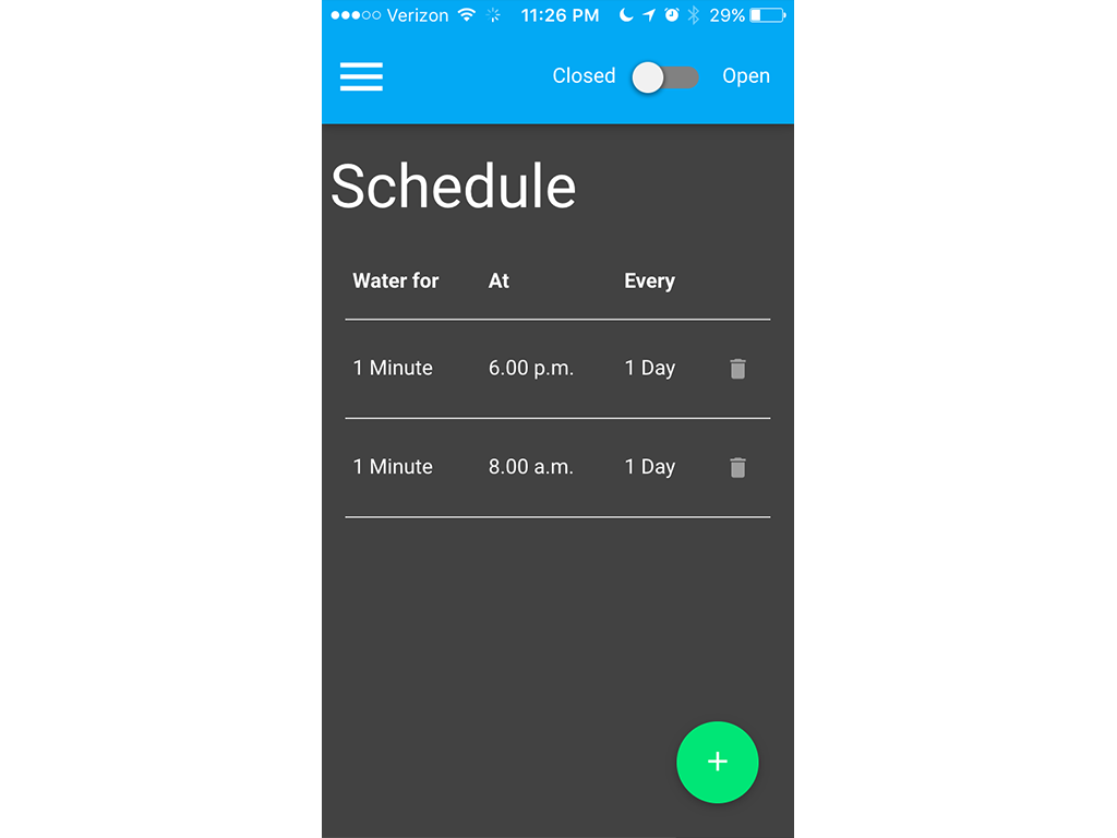
The main schedule screen on an iPhone 5s.
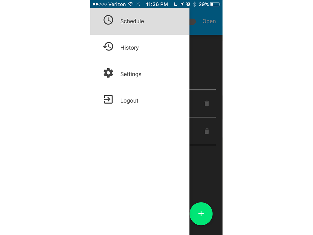
The responsive slideout menu on an iPhone 5s
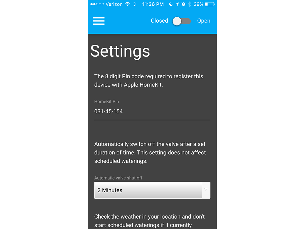
The settings screen on an iPhone 5s
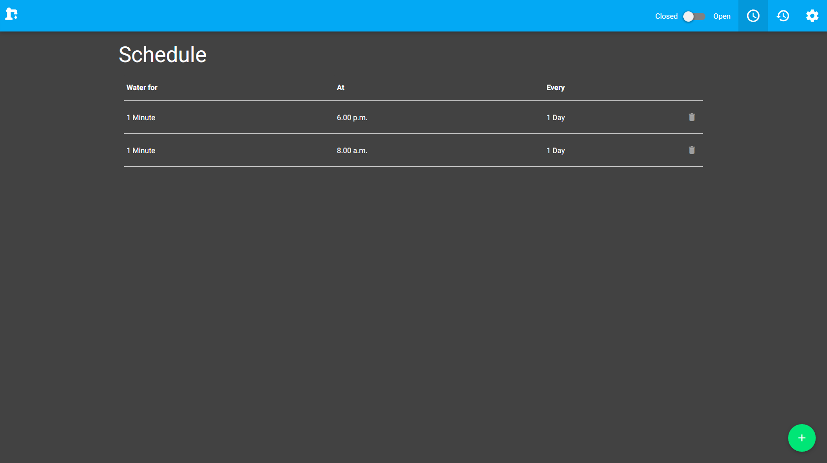
The schedule screen on a desktop browser
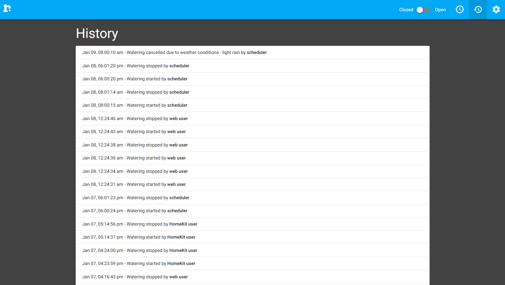
The history screen showing a list of all watering events
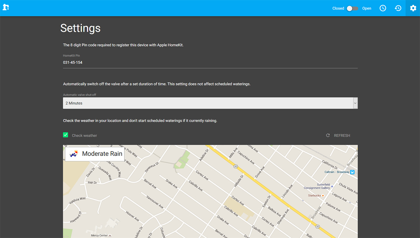
The settings screen on a desktop browser
Libraries/software used
As mentioned previously, the idea was to build a server that would run a scheduler and a web UI, so you can set up an automated schedule as well as control the device directly from a PC or smart phone. To put the web UI part of this together I used React.js, Redux, and MaterializeCSS on the front-end, and an Express based http server on the backend. With these together I was able to put together a nice responsive interface in a short amount of time. The most complex part of the UI was implementing the configuration interface for the weather based intelligent watering (I didn’t want to water the garden if it was already raining). To do this I used the Google maps API along with the HTML5 geolocation API to determine the users current location when they elect to switch on intelligent watering in the settings. With this I could collect the users latitude and longitude coordinates which I could pass into the OpenWeatherMap API to determine the weather in the users area. In addition to the web UI I implemented a scheduler which wakes up periodically to see if the user scheduled any waterings for the current time and runs the valve for a preset interval, unless of course intelligent watering is enabled, in which case it checks if its already raining and if it is, it doesn’t bother watering.
HomeKit and voice activated control
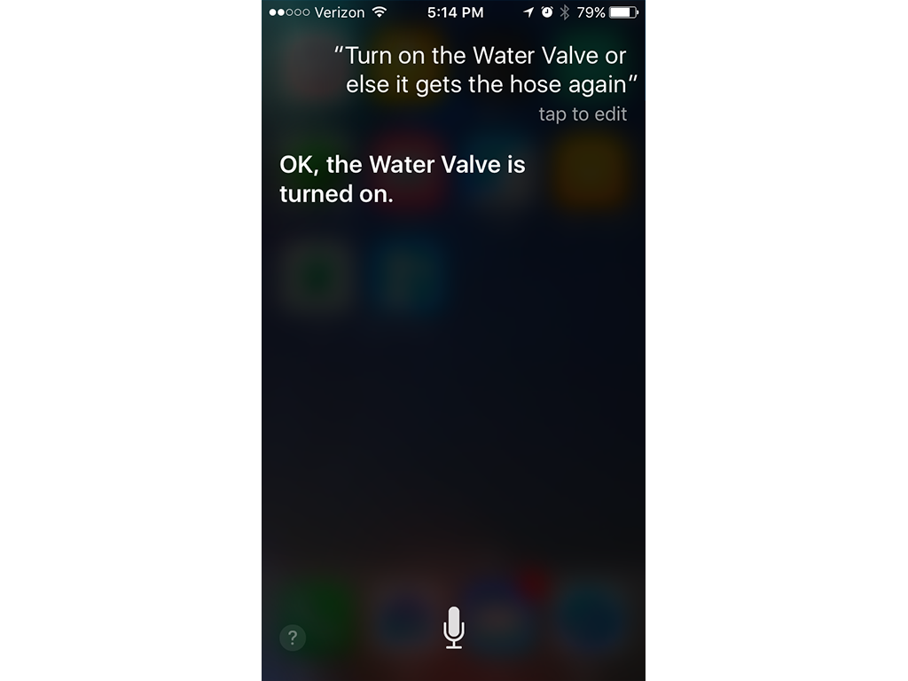
Asking Siri nicely to turn on the water valve
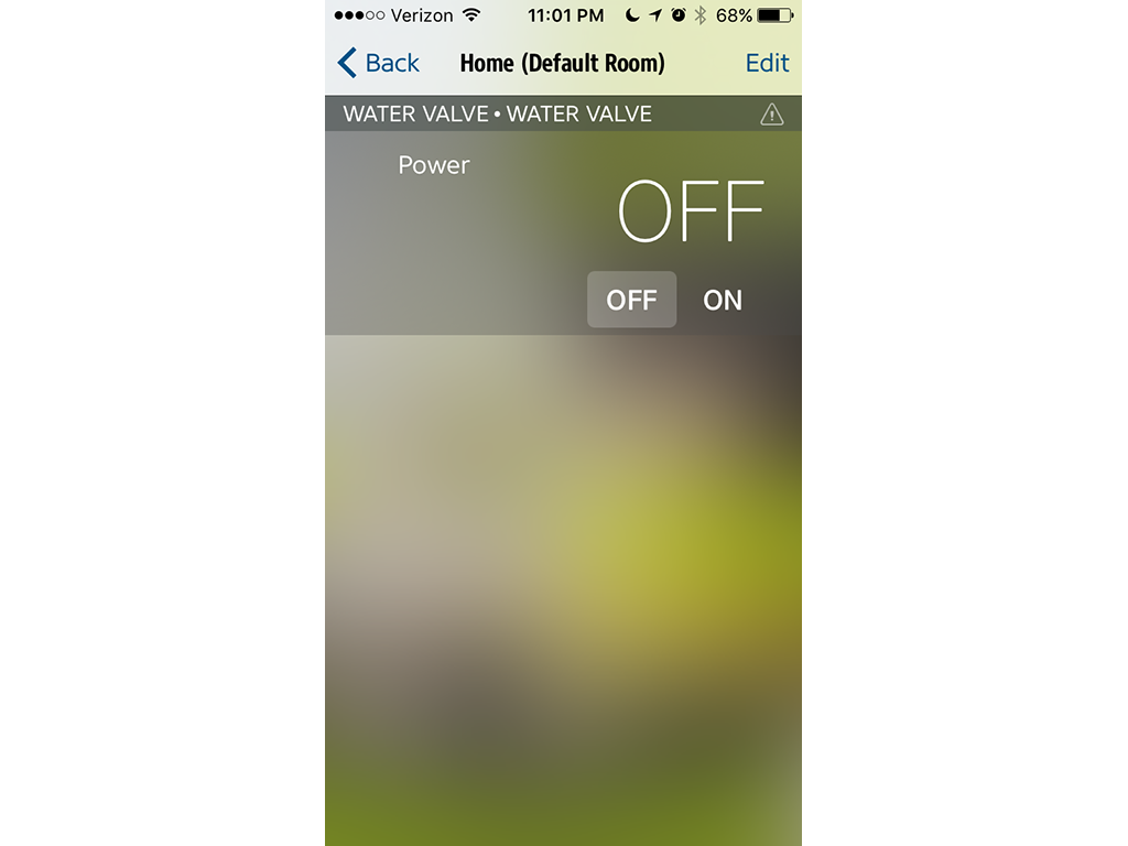
The water valve installed as an accessory into Eve
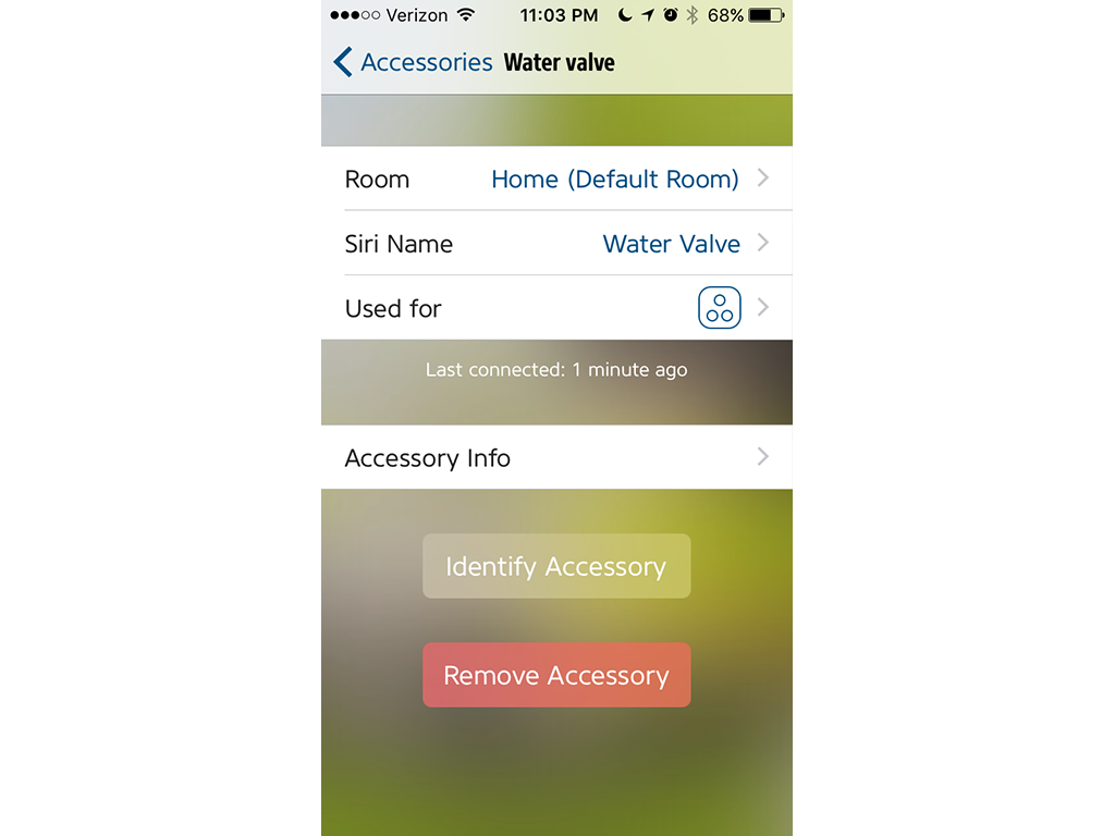
Configuration for the water valve HomeKit accessory
Libraries/apps used
While having an intelligent watering device with a webUI was pretty cool, I wanted to take it to the next level by adding integration with Apples HomeKit, and enable voice activated control via Siri. For this to work I needed to implement a server that implemented the HomeKit accessory protocol. Luckily theres a really good library for Node.js called HAP-NodeJS which makes this a fairly simple process. You need to feed into it some configuration information about your accessory, and provide some callbacks into the HomeKit events such as toggling the power status. The second step is that you need an app to add the accessory to your HomeKit ‘home’ (For some reason Apple don’t provide a built in app to do this), so in order to do this I downloaded the free Elegato Eve app. I can’t really speak to its quality for the more advanced HomeKit features, but its free and it did what I wanted which was to register my accessory with HomeKit, so I could use Siri to control the valve. Adding the accessory was simple - once I had the Hap-NodeJS server running on the PI, the water valve showed up as an accessory in the Eve app which I then added to my ‘home’. Once I did that I could tell Siri to switch the valve on and off, and it worked!