When I moved into my current place a few years ago there was an in-ground pool in the backyard. It was unheated & had no cover, so I ended up adding a heatpump as well as a safety cover so that it wasn’t a deathtrap for a young child. The cover is ‘automatic’ in the sense that the opening/closing action is electrically operated via a keyed switch, but I always thought it would be an interesting project to try and hook it up to some home automation so I could trigger the open & close without having to physically walk over to the switch and insert the key.
I finally got around to trying this out over the last few weekends & after reverse engineering the input & output electrics for the system & adapting/vibe-coding some previous Raspberry Pi automation projects, I came up with a solution that allows the cover to open & close via a web app or via HomeKit.
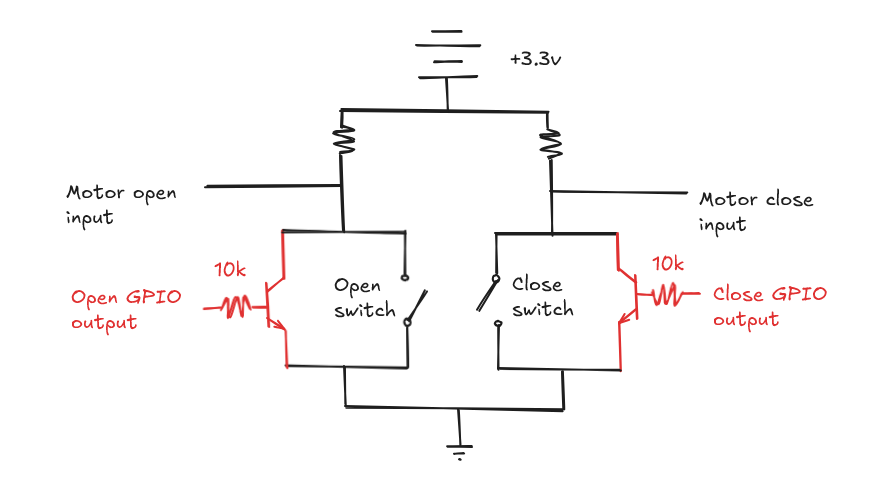
My specific pool cover is built by Latham, but I figure its probably a pretty common design for a lot of similar covers. It has 4 3.3v inputs - an input signal for opening the cover, an input for closing the cover (these are mutually exclusive and toggled via a physical key switch) plus two additional magnetic limiter switch inputs for the closed & open positions to prevent the cover over or under extending.
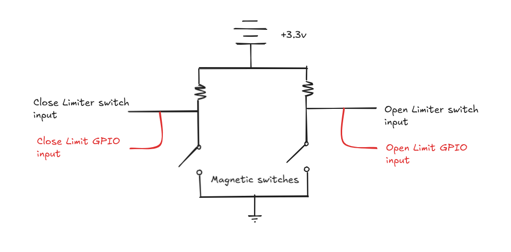
After splicing the wires to the key+limiter switches & fiddling around with a voltmeter while opening & closing things I figured that the actual circuit looks something like the diagrams below (in black) - basically a series of pull-up resistors connected to the pool covers logic board. I then figured that to control this via smart automation I would need to be able to tap into the signals, so I planned some additional modifications (in red), which would hook into the GPIO ports of a Raspberry Pi.
Motor switch circuit
Limit switch circuit
The app
Similar to some previous automation I’ve built - I put together a quick ExpressJS app running on a Raspberry Pi Zero that would control the 4 GPIO ports used to control the pool cover. I’ve posted the Source code on GitHub if you’re interested in building this project or adapting it for some other hardware.
The logic isn’t super complicated, but one interesting part of syncing the state of the physical hardware with the software is that the only way to know the true extent of how open or closed the cover is are the limiter switches at either end. This means that to get an interpolated state as the cover is opening or closing, I needed to add a calibration process which times how long it takes to open and close, and then uses that to estimate the position until the limiter switch gets hit and resyncs the true state.
One other interesting item I added to make the physical appearance of the app a bit more engaging was a WebGL caustics simulation to show the pool water. Rather than doing it from scratch, I adapted this one from ShaderToy but with a particular shade of blue.
If you already use Homekit for other home automation, the app also publishes itself as a Homekit compatible door accessory using HAP-NodeJS, so you can control it from Apple Home and hook it into any automation in that ecosystem
Installation
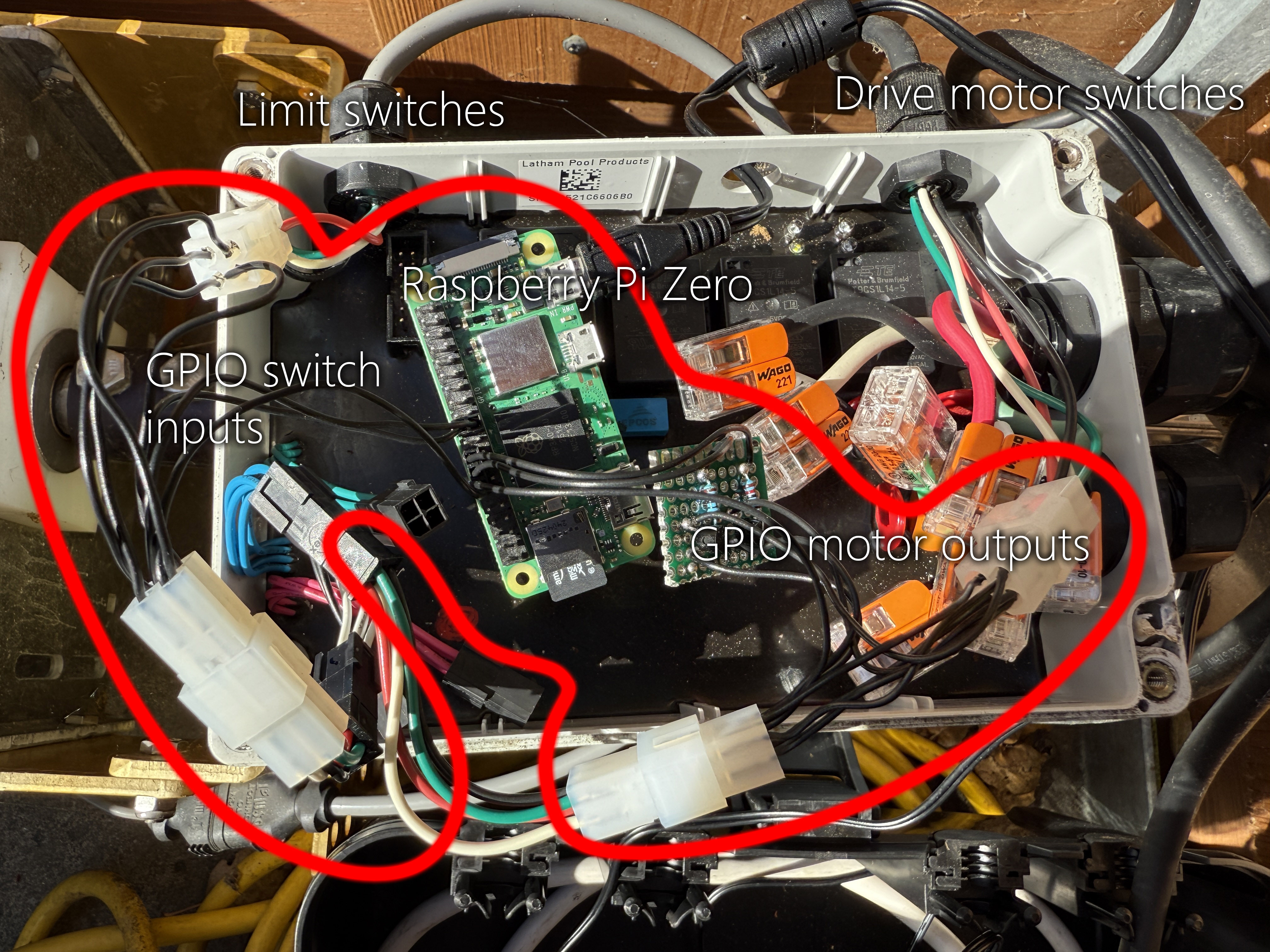
Below is the installation of the Pi on the physical hardware. For both the limit switches and the drive motor switches you can see I’ve spliced the existing wires with some molex connectors so that I can easily remove the automation if necessary. All the automation was already in a waterproof enclosure with plenty of free space - along with a pre-drilled hole for the Pi power cable, so I was able to just jam the Pi & the extra connectors inside without any additional modification.
I recently came across a discovery from my distant past. It didn’t seem like much at first glance, just a few text files of code forming a program written in an obsolete programming language, but it’s not an exaggeration to say that the direction of my life and career are all a direct consequence of this programs development and presumed destruction.
This is a story of the recovery of a long lost project, how I got it running again, and reflections on a youth well wasted.
It’s 1999 and I’m playing Total Annihilation. It’s a skirmish in the painted desert and the framerate is even slower than usual. My hard drive has started making ticking noises which are unfamiliar to me. This is unusual because I’ve internalized all the regular patterns of hard drive clicking and whirring that typically accompany my PC’s regular usage. The game also begins stuttering for seconds at a time, but things are still mostly playable, so I stick with it while the pauses get slowly worse until the game finally freezes completely. At first annoyed, then slightly anxious I conclude at this point that my game is over & a reset will probably be required. A few half hearted ctrl-alt-delete attempts later with no response this is confirmed and I have no choice but to press the reset button and wait for the BIOS POST sequence. The screen goes black, the PC speaker goes ‘beep’ and the POST screen appears, but from then on the sequence is different to the one I’ve seen a thousand other times. In the terminal I see the words: DISK BOOT FAILURE, INSERT SYSTEM DISK AND PRESS ENTER. I didn’t know what this meant yet, but I’d find out soon enough - they were telling me that my hard drive had just failed, they were telling me that I had just lost several years of work. Saved games I could get over, but I’d lost something more than that, I’d lost the source code to my unfinished masterpiece, an RPG I’d been writing in the first and only programming language I was aware of - QBasic.
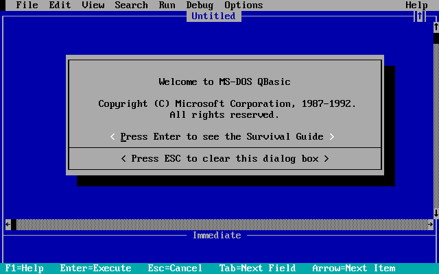
I’d been introduced to the concept of programming a year or two before by a friend. He told me there was this weird blue text editor where you could write commands and make the computer draw images and play sounds. I took a look on my windows 95 PC and sure enough, there it was, QBasic 1.1. I tried it out and despite experiencing the frustrations that I’m sure are familiar to any beginner programmer (wtf is a Syntax error?) I was hooked by the possibilities of what I saw, a blank slate upon which I could create whatever I wanted (if I was clever enough) - and what I wanted to create were games.
A blue screen full of promise
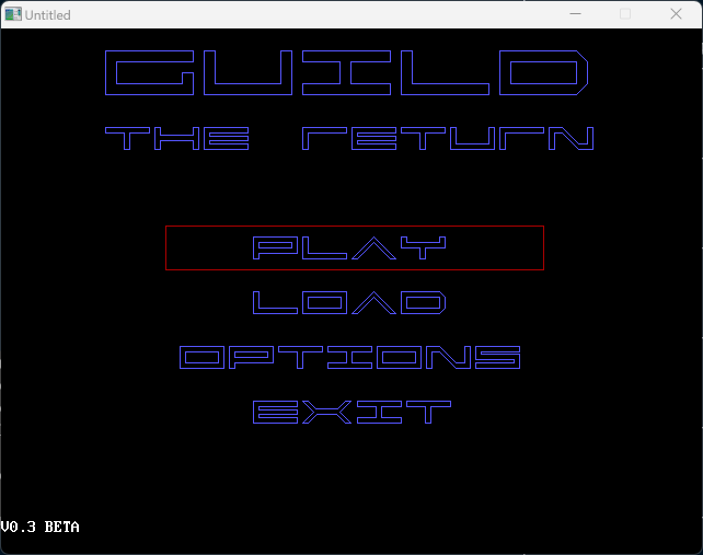
It didn’t really occur to me previously that games or software in general were things that people actually made. From my perspective they were just there and sometimes new ones came out, and some were better than others, but the notion of someone deciding to actually build a computer game wasn’t something I’d really considered. This newfound knowledge of programming changed that for me though and I started thinking through what it would take for me to create a game using QBasic. I spent enormous amounts of time in front of that blue screen, writing small demo’s and projects and slowly improving to the point where it seemed feasable to do something bigger (I also made my first money from software at this time, selling a QBasic learning course I created called QBasic for losers and angry loners - it sold 3 copies). The same friend who introduced me to QBasic in the first place shared similar interests and sensibilities, so we spent a lot of time comparing notes on how to solve programming problems and theorizing on how we could make the Best Game Ever. This all eventually cohered into an effort to build something that my 13 year old self considered relatively achievable. It was going to be an epic JRPG with the strange and awkward name of “Guild The Return” and it was going to have a huge sprawling plot, multiple characters, and a complex battle system.
Of course as we’ve already covered, things didn’t quite pan out and Guild would never be completed, but considering how little I knew and how limited the tools available to me - I actually got quite far. I wrote the beginnings of a story and built a couple of levels where you (a red square) could walk around some basic geometric environments, talk to other characters, solve some basic puzzles, buy items, and engage in questionably entertaining combat. To speed up development I wrote a level editor which allowed me to draw out environments in a rough paint-like interface. Performance was always a problem and I would be frequently stumped by QBasic’s limitations, but having near infinite time especially during holidays I could waste away days trying literally everything in the tree of possibilities until I found something that worked.
Once I was faced with the reality that all this was lost, I must admit I wasn’t really saddened, it was all too sudden and brutal and left me feeling more numb than anything else. I made myself a promise that I would always back everything important to me up in triplicate (which I have kept), and after briefly considering rewriting everything from memory, decided that maybe it was time to move on - I’d heard interesting things from a few friends about this thing called C & C++ which were what “real” games were made out of. That journey continued on into what I now refer to as my career and while I’ve still never actually completed a game, every new attempt has taught me something.
Returning to the present, for no real reason, I was digging around inside my “d:\installers” folder and seeing if there was anything worth keeping. It used to be where I would studiously keep copies of downloaded programs and their installers, but since the ubiquity of broadband it was largely unecessary and had become a junkyard I hadn’t looked at in many years. As I was looking around I found a folder named “floppies” and remembered that before I removed the last 3.5” floppy drive from my computer I had gone through my small pile of remaining disks and dumped their contents into this folder “just in case” there was anything useful on them. I must have done this sometime around 2009, because this was after Windows 7 was released, meaning that I no longer needed to use a floppy disk drive to install software RAID drivers for Windows XP (remember that thing about triplicate backups…). Anyway, I never really looked at what was there at the time, so I was curious enough to take took a look inside and noticed among a bunch of fragments of old DOS games & programs along with a bunch of files with the extension “.BAS”.
Those three letters are permanently etched into my brain, its short for “basic” and each file represented a QBasic program. I recognized the names of some of the programs and also saw a folder named “GUILD”. Clicking into it I saw the familiar names “LEVEL0.BAS”, “LEVEL1.BAS”, “BATTLE.BAS”, and a bunch of others. No way this could be what it looked like, but sure enough as I opened several of the files they contained QBasic code that despite the years still bore some familiarity and I had to conclude that perhaps Guild wasn’t lost to time after all.
I think what must have happened is that at some point I copied Guild over to one of those floppy disks in order to take it around to my friends house to show what I’d been working on. Before access to fast internet we’d frequently pass stuff to one another via floppy disk, and I ended up having a large pile of disks of various provenance covered with scribble and crossed out names and I didn’t really have any idea what was on most of them. I’m pretty sure I looked through my floppies after losing my hard drive and didn’t find any recent copies of Guild, but its quite possible I just didn’t check the right disks - or didn’t notice one disk at the bottom of a drawer or in a school bag. That disk must have at some point found its way into my final and dwindling pile of floppies that I finally copied over before dumping them years later.
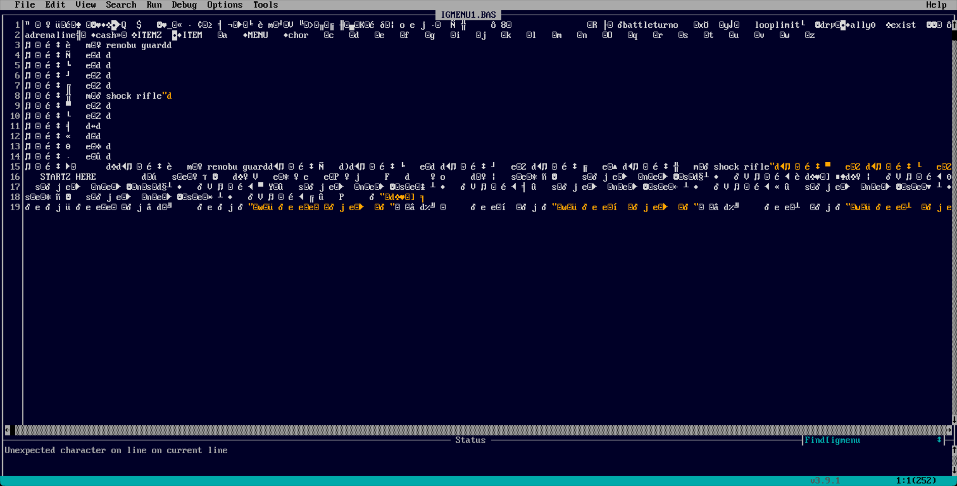
There was no way that whatever version of Guild and my other QBasic programs I had found were current with the versions that were lost in my hard drive crash, but maybe they were recent enough that a good chunk of the unfinished game was preserved. I took a look through some of the files and noticed that some of the .BAS files were corrupted (not surprising for floppies 10+ years old), luckily though it seemed no files related to Guild were affected so it seemed like there really was a possibility of seeing Guild run again after 25 years.
Not everything that was copied over survived
The Return of the Guild Returns - Getting it running again
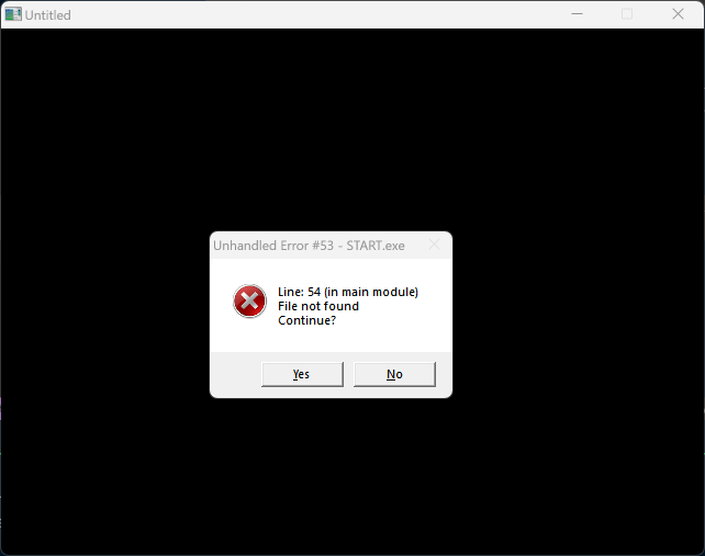
Now that it was sitting right in front of me I couldn’t resist trying to get it going. Luckily there’s a fantastic open source project called QB64 Pheonix Edition (a more active fork of the original QB64) that enables QBasic programs to run unmodified on modern operating systems along with providing some helpful new API’s. So I downloaded it, opened ‘start.bas’, and held my breath as I pressed ‘start’.
Not a good start
Unfortunately it turned out I was going to have to change quite a few things to get Guild working again, but I did this with the clear principle in mind that I would try to keep the original code (no matter how terrible) and game experience as similar as possible. The one exception I made to this was where I changed one of the locations in level1 from an empty corridor to an entrance to a shop so I could show an example of the shop system running (as I never hooked it up to anything originally).
Writing to the local filesystem
The reason that it was failing on startup was due to hardcoded absolute paths that were no longer correct, so I needed a way to get the correct relative path from the executable. I also needed to change it so the game would store save files within the users home folder instead of its own executable folder. In DOS & old versions of Windows programs were pretty much free to write anywhere in the filesystem they felt like, as such it was pretty typical for game to write save & temp files to their own directory. However on modern operating systems programs don’t usually have write access to their own directory, so I had to make some changes so that a directory could be created in the users home folder so the game could write files there instead. Luckily QB64 has some helpers to make this relatively easy, though the exact approach is a little different between Windows and OSX.
' Get the path relative to the executableFunctiongetAppDir$()IfInStr(_OS$,"WINDOWS")Thensep$="\"Elsesep$="/"EndIfgetAppDir$=_CWD$+sep$EndFunction' Get the path to the writable home subdirectoryFunctiongetDataDir$()IfInStr(_OS$,"WINDOWS")Thendatadir$=_Dir$("local data")+"\guild\"Elsedatadir$=Environ$("HOME")+"/.guild/"EndIfIfNot_DirExists(datadir$)ThenMkDirdatadir$EndIfgetDataDir$=datadir$EndFunction
Problems with state - its always state isn’t it?
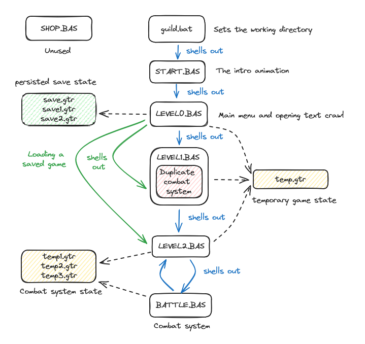
Now that I had fixed the issue with paths, I ran into other problems due to how the game was structured. The game was actually split into several separate executable files, which would then shell out to each other using the QBasic Chain command. In order to preserve the state of the game between these modules I also had to save state in a series of temp CSV files which I would then load from the newly chained module. The rough sequence of these looked like the following:
I'm not saying it's good, but this is how it worked
While this worked ok running in Windows 95, on a modern version of Windows this presented a number of problems. Firstly, QB64 programs don’t run in fullscreen, so its very obvious that when chaining to another executable, one window closes and another one pops up rather than appearing as a seamless transition. The other problem is that managing the state between these transitions was messy, with all the load/save code having to being copy pasted around multiple locations. I found a bunch of inconsistencies and level progression was actually broken in the version of the game I had - I had obviously been testing level2 and so level1 was being skipped entirely when starting a new game. Because of this I was going to need to refactor this especially as I wanted to stitch together as many of the levels & systems that were present in the version of the game I had.
As for the actual reason for this strange architecture - The original QBasic had a 160K memory limit for a given module. I wasn’t really aware of this at the time, but I found that at a certain point I was unable to run my game without getting a Program-memory overflow error. To fix this, my teenage self found that by splitting a program up into separate modules this error could be avoided!
Lucklily, QB64 doesn’t have any of these module size limits & now has an $INCLUDE statement to pull in code from other files, so I would be able to combine all the separate modules into a single executable. One thing that made this a lot simpler was the fact that my teenage self didn’t really understand how functions or subroutines worked, so all the code for these modules existed in the top level file scope, with global variables & goto’s for flow control. This meant that it was actually pretty simple to refactor each of these modules - I could just wrap the entire thing in a function & include it from the main entrypoint!
level1.bas BEFORE:
DimSharedfoo'... bunch of global variablesGotogamemenu:'... a bunch of codegame:'... a bunch of code
level1.bm AFTER
Functionlevel1Dimfoo'... bunch of locally scoped variablesGotogamemenu:'... a bunch of codegame:'... a bunch of codeEndFunction
For some of the more complex entrypoints like the battle system I had to convert the logic that loaded everything from a series of CSV file into some structs that could be then passed into the function. Where possible I tried to keep the variable names as close to 1:1 so I didn’t need to change the code within the functions themselves. The other nice thing about this change to the battle system was it made it possible to get the result of a battle and to persist changes to stats. Previously if you lost a battle the game would just close, and if you won the results of your changed stats would not actually be persisted.
Battle.bas before:
DimSharedbrangeAsIntegerDimSharedbatcashAsIntegerDimSharedturndefAsIntegerDimSharedaggressorAsIntegerDimSharedhealerAsIntegerOpen"c:\guild\temp3.gtr"ForInputAs#1DoWhileNotEOF(1)Input#1brange,batcash,turndef,aggressor,healer'... battle system code
Battle.bm after:
TypeBattleContextbrangeAsIntegerbatcashAsIntegerturndefAsIntegeraggressorAsIntegerhealerAsIntegerEndTypeFunctiondoBattle(contextAsBattleContext)'... battle system codedoBattle=1' victory!EndFunction
In doing some of these changes I found that there was significant amounts of duplicated code between the modules. For example, level1 contained its own mostly copy pasted version of the battle system that differed only slightly in how it handled loss conditions. I was able to delete this & instead call into the newly wrapped up battle system. Likewise the in-game menu was also replicated in each of the levels - I was able to condense this down to a single shared function.
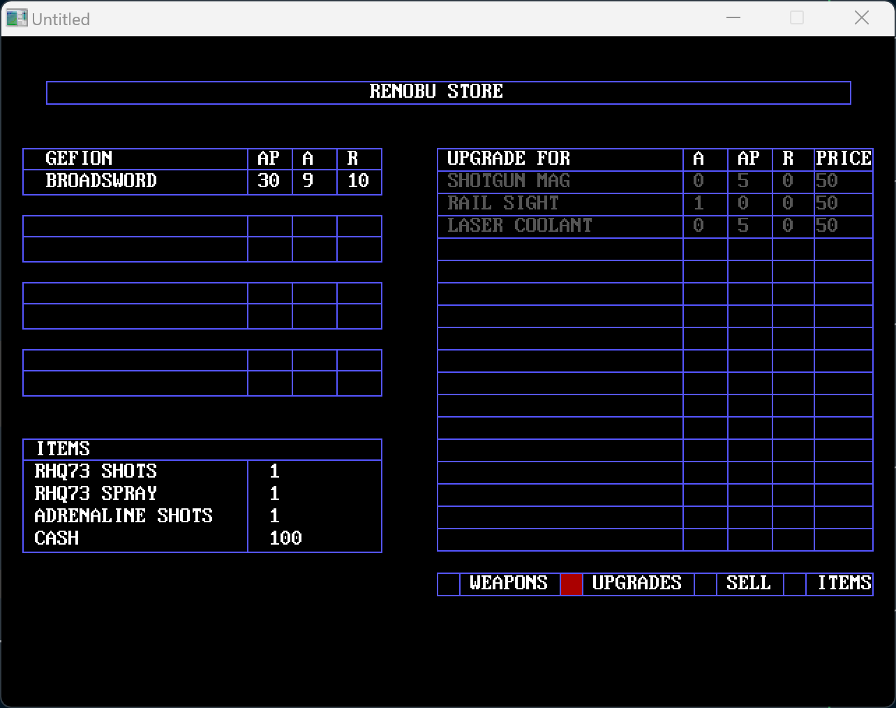
I also found that some modules were completely unused. As I mentioned above there was a fully functional shop system for buying items, weapons, and weapon upgrades. It must have been in a state of testing/development in the version I had, because the data for initializing the shop was hard coded at the top of the shop module so that it could execute independently from the rest of the game. I made a similar change to the one I did to the battle system so that other parts of the game could open the shop UI and populate it with items and upgrades. I decided that since the original game never actually used the shop I would try and insert it into an otherwise unfinished section of level1 - a doorway that in the original just gives you the message that ‘through this door is just a bunch of hallways’. Now going through this door takes you to the shop. I also noticed that while the shop allows you to purchase upgrades for weapons and buy multiple weapons for the primary character, the data model used and parts of the UI are obviously not adapted to these changes and it seems like it was a work in progress. For example there is no way to switch weapons from within the shop itself, you have to go out to the in-game menu and swap weapons if you want to switch a weapon to buy an upgrade from it in the shop.
A fully functional shop, but some of the features clearly weren't completed or thought through
With these changes, the levels themselves and various subsystems all resided happily within a single module. The last step was to fix the state machine that determined how to start a new game, how to load an existing game, and how to progress between levels now that the previous logic of shelling out to new levels was removed.
Load/Runloop logic before:
' copy pasted wherever a module transition happenedOpen"c:\guild\temp.gtr"ForInputas#1DoWhileNotEOF(1)Input#1,GAMEPLACE,cash,rhq73i,rhq73s,adrenalineLoopClose#1' this is what was called from the load screen, other places' would just directly chain to the module requested.SelectCaseGAMEPLACECase1' Chain "c:\guild\level1.bas"Case2Chain"c:\guild\level2.bas"EndSelect
Load/Runloop logic after:
TypeGameStateGAMEPLACEAsIntegercashAsIntegeradrenalineAsIntegerrhq73iAsIntegerrhq73sAsIntegerEndTypeDimSharedstateAsGameState' from within the main menuloadState(state)runGameSubrunGamelevelResult=0DoSelectCasestate.GAMEPLACECase0:levelResult=level0Case1:levelResult=level1Case2:levelResult=level2CaseElse:levelResult=0EndSelectIflevelResult=1Thenstate.GAMEPLACE=state.GAMEPLACE+1saveStatestateEndIfLoopUntillevelResult=0EndSub' in level0.bmFunctionlevel0' ... rest of the intro, always transitions to level1level0=1EndFunction' in level1.bmFunctionlevel1'...' if the user selects return to main menu from the ingame menulevel1=0'...' if the user completes level1level1=1EndFunction
After making these changes, the game actually started up & I could navigate the main menu!, but one thing I noticed was all the animations were playing far to quickly, so there was obviously some problem with the animation timings that I would have to fix.
It loads!
System speed compensation
The original QBasic (to my knowledge) had no way of sleeping for less than one second & this was a problem if you wanted to control the speed of animations or gameplay elements across different PC’s. Nowadays QB64 has some commands to solve this, but my teenage self originally solved it using some busy waiting as shown below
Print"COMPENSATING FOR SYSTEM SPEED....."second=0exitsleeping=0TimerOnOnTimer(1)GoSubexitsleep'wait for one second and break out of the loopDosecond=second+1LoopUntilexitsleeping=1Print"DONE"exitsleeping=1' to wait half a seconda=1Doa=a+1LoopUntila>(second/2)
I remember I was extremely proud of myself when I came up with this clever hack, unfortunately this approach didn’t seem to work at all on modern machines, the busy waiting loop executed in pretty much no time meaning all animations were far too fast. I didn’t look into it really closely, but I suspect the second variable was actually overflowing from being too large, resulting in the waiting loop not actually doing nearly enough iterations to slow the machine down. I ended up just ripping this code out & replacing it with QB64’s _Delay command which takes a floating point number & can wait for intervals as small as 10 milliseconds which was fine for my usecase.
Part of the games intro sequence
Lets Play!
Now aside from a few small bugfixes & tweaks the game was playable! As I played through I realized that probably 70% of the final content I had from the lost version was still present. Rather than summarize, I figured it would be more fun to just record a lets play. Watch as I cringe in embarrassment at my own writing and design decisions.
Interesting observations & trivia
While just playing through the game was a blast, I had almost as much fun rememberring all the little tricks, methods, and tools I’d used to make the game as well as accessing a time-capsule of my then very rudimentary knowledge of software development. As I looked through the code and replayed the game I kept note of a few of the more interesting observations & I’ve included them below.
My first stack overflow
Looking back the biggest difference in learning programming in 1998 vs 2023 (even if we exclude recent developments like LLM’s) was that without regular access to the internet, I was limited to what I could find out through trial and error and without information beyond the included help documentation (which was not particularly readable to someone without a formal CS education). Because of this, I often encountered issues the cause of which I didn’t really understand and I would just try different things until the error went away. This built some intuition of things to avoid, but not a solid grounding of exactly why.
My most vivid memory of this is encountering a “stack overflow” error when navigating around the in-game menu’s of my game for too long. I remember that the pattern I was using was to handle any user input, then call the menu function again - something like the pattern below
Functionmenu()' ... render the menuDokey$=InKey$SelectCase(key$){' ... handle user input & change state}menuLoopEndFunction
Now anyone who knows about how function calls actually work can immediately see that this is unbounded recursion and will eventually exhaust the available stack space. Of course, I didn’t know anything about memory allocation or stacks, but I did eventually figure out that if you just keep calling a function without returning, you would eventually see this error, so I rearchitected the menus to something like below to avoid this problem. I also added a bunch of comments in all caps saying that 'THIS CANNOT RUN OUT OF STACK SPACE FOR ANY REASON!!!!!!, so I was obviously proud of myself.
Functionmenu()DoGoSubhandleInput' ... render the menuLoophandleInput:key$=InKey$SelectCase(key$)' ... handle user input & change stateEndSelectReturnEndFunction
An incomplete map editor
This was the last thing that I worked on before losing the game originally, and as such this differed the most from the map editor in the version of the game I salvaged. In this version you could draw rudimentary maps on the screen, but I remember that in the lost version I actually built a system to load and save these maps and could export them into a series of QBasic draw commands that could be added directly to the game. I ended up using this tool to build a more fully navigable space in level1 which I also updated to use the free-form movement system and interface used in level2. It would have been amazing if this had been preserved as it was probably the most graphically complex environment I built, but unfortunately this was definately lost.
A keyboard driven UI, I didn't know how to enable mouse support at the time
Handmade fonts
One thing I realized very early on in the game’s development was that I was going to need to draw a lot of text & QBasic had no support for rendering custom fonts - so I devised my own custom font that I could re-use throughout the game’s user interfaces and menus. The way this worked is QBasic has a draw command, that similar to the HTML5 Canvas 2D rendering context. You can pass it a series of instructions to draw lines, set colors etc, but in the case of QBasic you pass this as an encoded string e.g. DRAW "c9 e20 f20 l5 h15 l5 br45" draws a capital “A”. To render characters my font I wrote out draw commands for each letter of the alphabet and stored the command strings in a CSV file. Then to open and draw the custom font I did the following.
OpengetAppDir$+"alphabet.gtr"ForInputAs#1DoWhileNotEOF(1)Input#2,a$,B$,c$,d$,e$,f$,g$,h$,i$,j$,k$,l$,m$,n$,o$,p$,q$,r$,S$,t$,u$,v$,w$,x$,y$,z$LoopClose#1'To draw a wordDRAW$pDRAW$lDRAW$aDRAW$y
Which renders as
Overlays & reducing flicker with XOR
A problem I constantly had with QBasic was flickering animation. It wasn’t possible to do double buffered animation in Screen mode 12 (640x480) which I was using for the game (and I didn’t know how to do double buffered animation anyway). Clearing the screen, then redrawing the screen introduced horrible flickering, so I had to find workarounds to only clear the minimum amount of the screen possible in order to animate things.
One way I found to do this was to use the Xor (Exclusive OR) boolean operator when drawing. The way this worked is that the Put command for blitting a sprite to the screen could also include a boolean operator that would take the existing screen pixel and apply the operator to the sprites pixel. In the case of Xor it has the useful property that A Xor B Xor B == A, which means if you render a sprite over an existing image, and then re-render over it again it disappears, giving you flicker free animation. The funny thing about this is that I didn’t know anything about boolean algebra at the time and had no idea what Xor was really doing, I found this purely by chance and saw that adding Xor magically worked for my purpose.
Of course the problem with this is that the first Xor changes the colors of your original sprite - so I had to work around that, but in some cases this was actually useful as shown below where the location names on the map are written in a color that appears to be highlighted over the background. This works by overlaying a white font with a black background using XOR.
Notice how the fonts appear highlighted over the background
Music streaming
On the main menu there’s a repeating song in the background. QBasic allows you to play sounds in two modes, in the foreground - where it blocks all execution of commands until the sound completes, or in the background where the sound plays while the program continues to the next instruction. This means that if you want to have music along with any interactivity, you need to use the background mode (denoted by mb below). The problem with this is that you periodically need to refill the background music buffer, but you also don’t want to overfill the buffer because there’s no way (that I knew of) to stop the music in the background buffer until it empties out.
The way I dealt with this was to break up the title song into blocks of 4 notes & when the background music buffer had less than 2 notes left, insert the next 4 notes. This meant that the music played continuously, but if you selected ‘New Game’, and I wanted the music to stop - the music would stop after at most 6 notes, rather than playing through the entire song. Essentially I built a very crude music streaming system.
TimerOnmusicstate=0OnTimer(1)GoSubmenumusicmainmenumenumusic:Ifsettings.sounds=1AndPlay(1)<2ThenSelectCasemenustateCase0Play"mb L7 G3 D"Case1Play"mb L7 G- G B G"Case2Play"mb L7 C3 < G"Case3Play"mb L7 o3 B > C C < B > "Case4Play"mb L7 o3 G3 D"Case5Play"mb L7 o3 G- G B G"Case6Play"mb L7 o3 C3 < G"Case7Play"mb L7 o2 B > C C < B > "Case8Play"mb L7 o3 G3 D"Case9Play"mb L7 o3 G- G B G >"Case10Play"mb L7 o4 C3 < G"Case11Play"mb L7 o3 B > C C < B > "EndSelectmenustate=menustate+1Ifmenustate>11Thenmenustate=0EndIfReturn
Particle effects
Particle systems are one of my favorite things to mess around with in computer graphics, I must have written dozens of them over the years, but the ones I wrote for Guild were my first. I wrote two separate particle effects in the game. The first was as part of an alternate intro sequence (which I integrated into the main game), and the second was part of the games only real puzzle.
The intro particle effect works by taking an array of coordinates for the “8” logo and offsets them by a radius & an angle and then iteratively reduces the radius and angle to create a whirlpool like effect where the logo gradually appears from a random field of dots. Luckily I’d already learned a bit of trigonometry at school, so some basic usage of sin & cos were enough to make this work.
Setting high expectations with the intro sequence
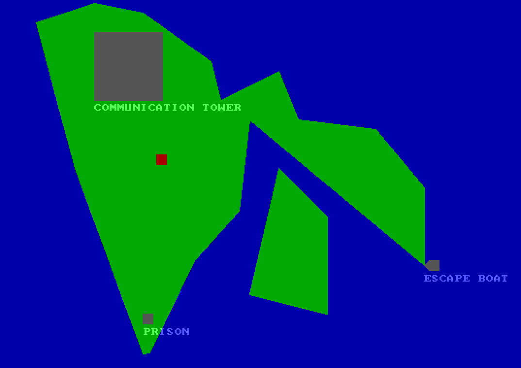
The second effect was one I built as the payoff for the only puzzle I built for the game. The premise was that you needed to break into a prison complex where your team was being held, but the fence around it was electrified. Conveniently there was a power generator building nearby and you could adjust the power level to overload the generator and blow it up, disabling the fence.
This was the most complex effect in the whole game, and it worked in several stages. First I drew a series of yellow and red lines at random radii and angles outward from the center of the building to simulate the actual explosion itself. Then to fade out the explosion and show the wreckage I used the same effect, but replaced the red and yellow with green and brown so that it looked like only a crater remained. The final part was to show smoke drifting away and I did that by creating a field of randomly displaced dots and then have them move in a uniform direction to look like they were being blown in the wind.
Not a very well designed puzzle, but a fun payoff
Goodbye, but not the end
I really enjoyed getting Guild working again but this is almost certainly the last time I will program anything in QBasic. Writing this post also ended up being a cathartic experience, and I feel I’ve finally given Guild the proper send off long after its abrupt departure.
At this point, I’m happy for what it is and that it will remain unfinished forever.
(I’ve also put the source up on GitHub, but I really don’t recommend looking at it)
Getting another chance to experience my long-lost work again reminded me that most creative pursuits don’t hold up well over time, but it also reminded me that its not the artifacts themselves that are important. Revisiting something you’ve made allows you to revisit some of your state of mind that bought that thing into being - thats what’s valuable. In my case, being able to channel that feeling that I had staring at that blue terminal all those years ago, watching the blinking cursor and thinking that if I wanted to, I could build just about anything. While many details of my life have changed since then, I realized that I still get that feeling from time to time staring at a blank editor, that feeling hasn’t changed a bit, and I hope it never does.
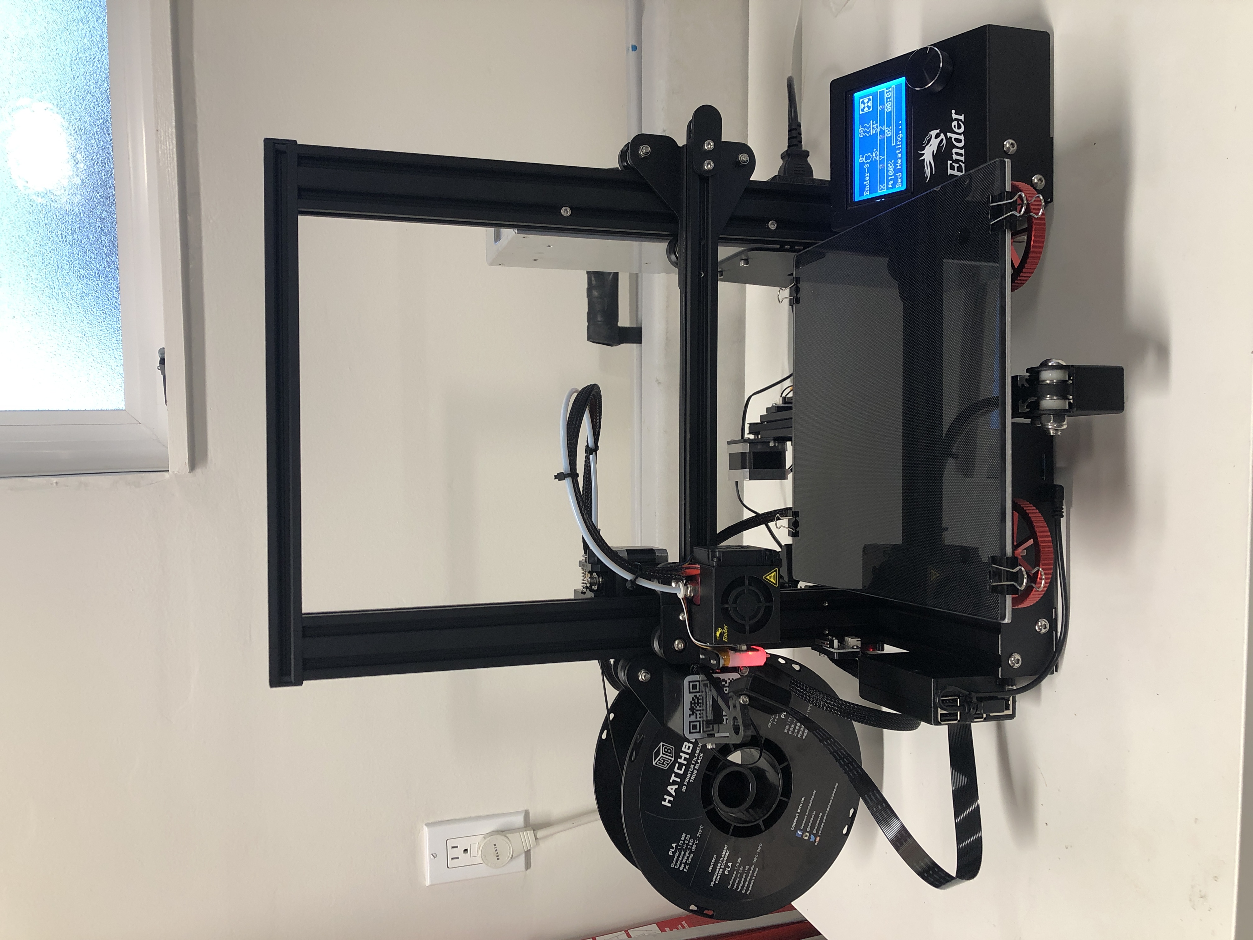
I’ve been interested in 3D printers for a while now, in particular the thought of being able to take some.of.my. hardware projects to the next level with custom printed cases & components was very compelling to me. So I decided recently to take the plunge and purchase my first 3D printer to see if my expectations matched whats available.
I decided to get the Creality Ender 3. Its one of the cheaper printers on the market, but its got a great reputation & a huge modding community that means you can with a few tweaks have access to features of much more expensive printers. The downside is that its very much the opposite of plug and play - expect to spend days or weeks putting it together, deciphering poor documentation, flashing custom firmware, wiring in mods, & printing out additional parts. With that said I kind of enjoy doing all of the aforementioned things and after spending a long weekend messing around with it, everything is running well.
What follows is a list of the various things I learned along the way & some of the mods & enhancements I added to get to my current setup
Gotchas
The Ender 3 comes in a number of different variants & its not clear which one you’ll be getting when you purchase one. The biggest difference I could see is that some older models come with an 8bit mainboard, whereas newer ones come with a 32bit mainboard (of which there are also two variants 4.2.2 and 4.2.7). The 32bit board is much better - it comes with a bootloader which means you can flash new firmware from the SD-Card & don’t need to load one with an Arduino. It’s also much easier to wire in mods like the BLTouch as it has a dedicated port and doesn’t need any adapter boards.
The default Creality firmware doesn’t save settings to EEPROM, it uses the SD card & they don’t seem to document this anywhere, so if you’re trying to save settings and its not working - thats why. In my case I use Octoprint to print from USB (more on that later), so I can just leave an SD-Card inserted at all times.
Ender 3 (& most consumer printers) are FDM printers which means they build a model by layering many layers of filament over one another. This means that printing certain geometry is difficult - things like overhangs or roofs will need support structures to stay up while printing & models without a firm base will need extra skirts to stick well to the printer bed. There’s usually an optimal way to design or align a model for printing that minimizes the amount of throwaway support material you’ll need.
3D printers don’t typically print 100% solid parts, they save material by specifying a percentage of ‘infill’ and leave the rest of the internal structure of a model hollow. For most models that don’t need strength you can get away with 20% infill, but if your model needs more structural strength you’ll need to up this percentage.
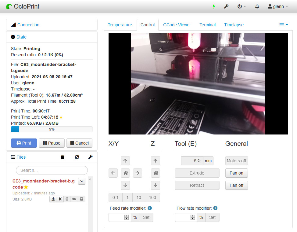
Octoprint
OctoPrint is a fantastic piece of software that allows you to remotely control your printer from a Raspberry Pi, including uploading new prints & even viewing a live video stream of the current print status. To set it up I used this guide, but I opted to use a different case for the Pi so I could side mount it and not have to run the camera cable underneath the printer.
You’ll need to tape over 5v USB pin as sending power to the printer through the Pi does weird stuff like having the printer screen powered on while the main power supply is actually off.
Make sure the micro USB cable has data sync support, not just 5v/gnd otherwise OctoPrint will not be able to connect to the printer. You’d be surprised how many micro USB cables are charging only - I had to try 3 I had lying around until I found one.
Creality firmware sends doubled temperatures. OctoPrint warns you, but you’ll need to install this plugin to fix it.
Fire-safety
3D Printers get hot & the cheaper ones are often made with cheaper components, so you probably shouldn’t leave them running completely unattended for long periods of time & you should probably take some basic safety precautions to prevent the most likely causes of a fire.
Update the firmware to ensure you’ve got thermal runaway protection.
Add a fan shroud so that filament doesn’t get into the mainboard fan.
Upgrade the PSU if you want - here’s a guide to switch to a quieter and more reliable MeanWell PSU.
Get a smart plug to provide a direct power cutoff in case the printer PSU or mainboard has a failure. I used a hue switch like this.
Install OctoPrint ‘Temperature Failsafe’ plugin & Use a shell command in the plugin settings to the smart plug to disable the power if the temperature goes over what you expect (see here for how to get the user id & switch id for your Hue switch). Once this is set up you can install the ‘PSU control’ plugin and use a similar command to power the printer on/off remotely.
curl -X PUT -d '{"on":false}' http://192.168.0.4/api/<hue-api-user-id>/lights/<switch-id>/state
Improve printing
Get an auto bed leveller like BLTouch. You’ll have to update the firmware for this, but it makes it much simpler on each print as you won’t have to manually level the bed. Also Note 4.2.2 boards don’t need a 27pin adapter, they have a dedicated port that you can just plug in directly.
Get a glass bed for better adhesion (I use this one - I also use it upside down as the non-coated side sticks better in my experience).
Move the filament spindle to the side for a better filament path. I used this bracket.
Swap out the default springs for a longer lasting level. I used these.
Slicing & Cura
Once you’ve downloaded a 3D model, you’ll need to ‘slice’ it to convert it into GCode instructions that your printer will actually execute to print the model. A popular free program for doing this is Cura & below is the start and end snippets of GCode you can configure it to run before & after every print. These snippets are important as your printer needs to pre-heat, home itself, clean the hot end, and home itself before it will be able to print successfully.
Start GCode
; Ender 3 Custom Start G-code
M140 S{material_bed_temperature_layer_0} ; Set Heat Bed temperature
M190 S{material_bed_temperature_layer_0} ; Wait for Heat Bed temperature
M104 S160; start warming extruder to 160
G28 ; Home all axes
G29 ; Auto bed-level (BL-Touch)
G92 E0 ; Reset Extruder
M104 S{material_print_temperature_layer_0} ; Set Extruder temperature
G1 X0.1 Y20 Z0.3 F5000.0 ; Move to start position
M109 S{material_print_temperature_layer_0} ; Wait for Extruder temperature
; G1 Z2.0 F3000 ; Move Z Axis up little to prevent scratching of Heat Bed
G1 X0.1 Y200.0 Z0.3 F1500.0 E15 ; Draw the first line
G1 X0.4 Y200.0 Z0.3 F5000.0 ; Move to side a little
G1 X0.4 Y20 Z0.3 F1500.0 E30 ; Draw the second line
G92 E0 ; Reset Extruder
G1 Z2.0 F3000 ; Move Z Axis up little to prevent scratching of Heat Bed
; End of custom start GCode
End GCode
G91 ;Relative positioning
G1 E-2 F2700 ;Retract a bit
G1 E-2 Z0.2 F2400 ;Retract and raise Z
G1 X5 Y5 F3000 ;Wipe out
G1 Z10 ;Raise Z more
G90 ;Absolute positioning

G1 X0 Y{machine_depth} ;Present print
M106 S0 ;Turn-off fan
M104 S0 ;Turn-off hotend
M140 S0 ;Turn-off bed

M84 X Y E ;Disable all steppers but Z
Next steps
I’m now printing pretty reliably good prints with PLA, so the next thing is to familiarize myself with Blender so I can put together some custom 3D models to print. The first project I want to tackle is a custom tenting mount for my ZSA Moonlander keyboard - If thats successful I’ll post the results up here in future.
Update: I did end up creating the moonlander bracket. You can check it out here. Its also listed on the ZSA printables page here.
Posted on Apr 15, 2020
programmingautomationopenwrtnetworking
So like most people at the moment I’m stuck at home as part of the ongoing quarantine for Covid 19 & thankfully I’m fortunate enough to have a job where I can work from home. Unfortunately having most of the neighborhood at home streaming, video-calling, and also working from home during the day is wreaking havoc with the local internet infrastructure and my ISP is not coping well with the added load. This has resulted in multiple several-hour dropouts of my connection and several days of work time effectively lost. Now with that said, I do have a backup connection in the form of my iPhones LTE connection which I can connect through using its wifi hotspot - but it’s limited in how many devices can connect to it concurrently & its also a pain to have to manually connect on every device that may need to access the internet during that time (especially home automation devices where switching WIFI is a pain).
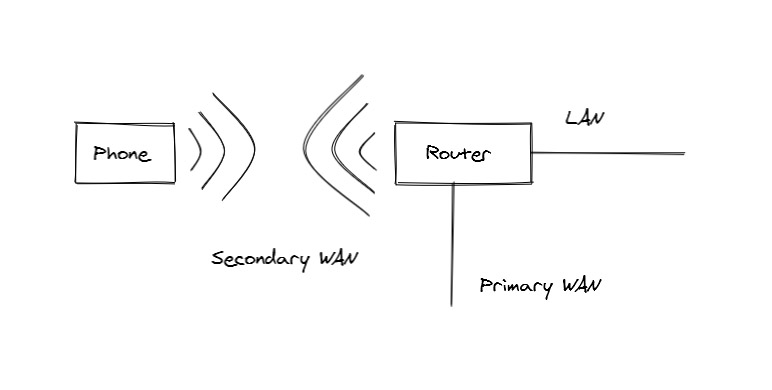
So I decided to see if I could set up my home network with an automated failover system that would (in normal circumstances) have my main router use my cable internet as its WAN connection & then when that drops, have my router connect as a client to my phones WIFI hotspot and use that as its WAN connection. Also importantly I wanted to do this cheaply and not have to purchase any expensive enterprise networking hardware.
After investigating it turns out that my router does support Dual WAN failover, but it can’t connect to another WIFI network in client bridge mode to share the connection (well maybe it can with a different firmware like DD-WRT but I’m happy with the AsusWRT Merlin firmware I’m running, so I didn’t check). So I started looking around for a device that did support client bridge mode and came across this cheap TPLink travel router, you can pick one up for $35 and in addition to solving my main problem, its also a handy device to take with you when travelling for sharing WIFI & hotspot connections etc.
However once I actually got my hands on one I found a problem. For whatever reason, the stock firmware doesn’t work in the configuration I wanted. I set up the dual WAN on my Asus router & set the TPLink up to connect to my phones hotspot - but the Asus couldn’t get a DHCP lease from my phone and nothing connected to the Asus could access the WAN. I played around with all the settings I could, but couldn’t get it to work - so I decided to ditch the stock firmware on the TPLink and install OpenWRT instead to see if I would have any more luck. Getting OpenWRT installed was a bit quirky, but ultimately not too difficult - you just need to follow the instructions here.
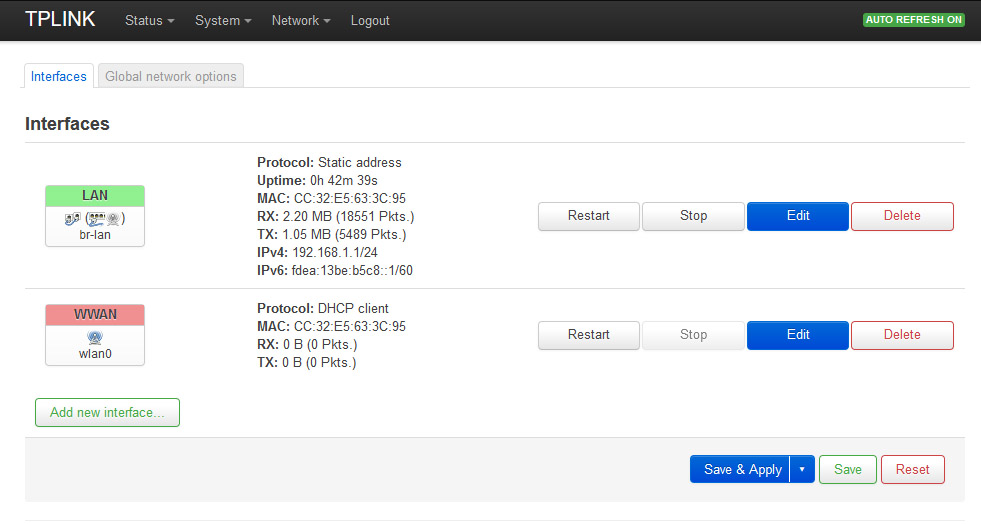
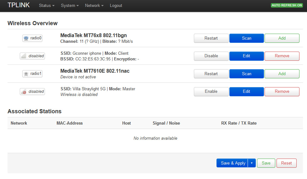
Once I had OpenWRT up and running I had to set up two network interfaces. A bridged LAN that runs on the 5GHz radio and the ethernet port, and a WAN that runs on the 2.4GHz radio. Once that’s set up you just need to set up the 2.4GHz wireless to connect in client mode to the hotspot (and I also set up the 5GHz wireless as an access point to my existing WIFI network).
Finally the TPLink has a slider switch that allows you to switch ‘modes’ (i.e. access point, ethernet sharing, hotspot) when using the stock firmware - this is a useful feature but doesn’t work out of the box with OpenWRT, but since I only want the 5GHz radio running as an access point when I’m travelling (I already have good coverage at home with my existing router, so I don’t need the extra access point) - I wanted to be able to switch this on/off without having to log into the configuration UI. To do this there’s an open source package called openwrt-slide-switch which adds support for this. To install I needed to enable SSH on the TPLink and once logged in run:
opkg update
opkg install slide-switch
You then need to configure the actions to take when the slide switch mode is changed. To do this, you need to add a couple of files into /etc/rc.button (and make sure they are chmodded to +x). The README on the github page above has all the details, but I ended up adding two ‘modes’ - one which enables the 5Ghz access point, and one which disables it.
With all this configured if my main internet connection goes down, I just need to enable my phones wireless hotspot and the TPLink will connect and automatically bridge the connection to all devices in the house until the main connection comes back online again.
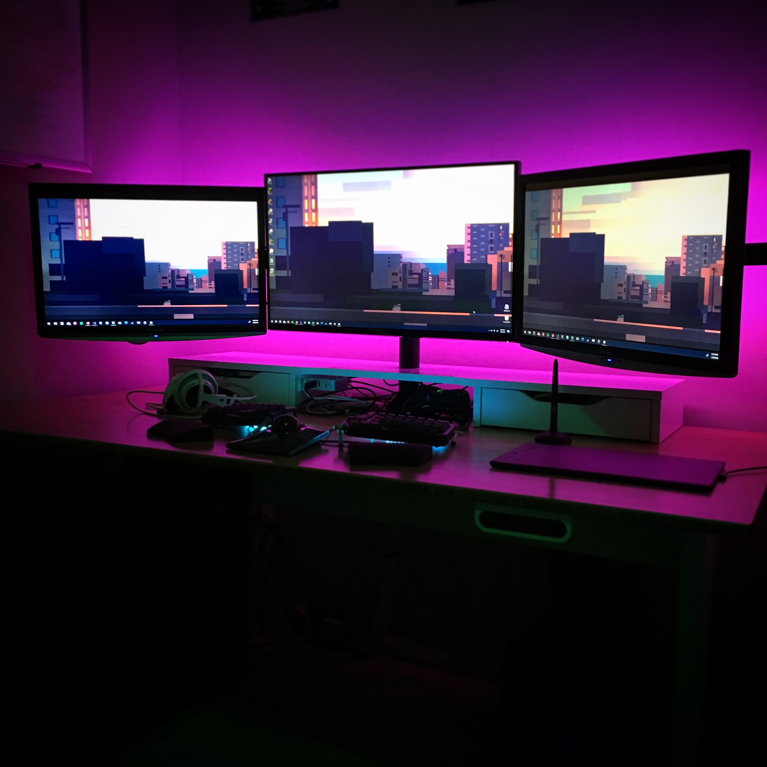
So of late I’ve been on a bit of a home automation binge. I’ve added a bunch of Philips Hue bulbs around the house along with some smart switches and light sensors. While you can integrate these in with a first party Philips app, Apples HomeKit, or Google Home and configure some pretty interesting stuff including timers, IFTTT triggers, & voice control - I wanted some very specific behavior for the backlighting strip I installed in my home-office that would require some manual hacking.
Specifically, I wanted the strip light to switch on and off automatically based upon whether my desktop PC was powered on or asleep and since the Philips Hue accessories can be fully controlled via a JSON API, it was pretty simple to whip up a quick c# script to accomplish this. I’ve included the full source below, but the basic jist is that the script is set to run as a windows Startup item & listens for power events and tells the Hue Bridge to toggle the specified light based on whether the PC is powering off or waking up.
Source code
usingMicrosoft.Win32;usingNewtonsoft.Json.Linq;usingSystem;usingSystem.Collections.Generic;usingSystem.Linq;usingSystem.Net.Http;usingSystem.Threading;usingSystem.Threading.Tasks;usingSystem.Windows.Forms;namespaceLogoffLightsOut{staticclassProgram{// put in the IP address of your Hue bridge hereprivatestaticreadonlystringHueBridge="http://<ip_address_of_hue_bridge";// put in the user ID & UID of the light you want to control here// You can find these values by following the getting started guide here// https://developers.meethue.com/documentation/getting-startedprivatestaticreadonlystringHueUserId="hue_user_id";privatestaticreadonlystringHueLightUid="hue_light_uid";privatestaticreadonlyHttpClient_client=newHttpClient();privatestaticstring_hueLightIndex;privatestaticbool_exiting=false;[STAThread]staticvoidMain(){_hueLightIndex=Task.Run(async()=>awaitGetLightIndex()).Result;Console.WriteLine($"Found light at index: {_hueLightIndex}");Console.WriteLine("enabling light...");Task.Run(async()=>awaitSetLightState(true,4));SystemEvents.PowerModeChanged+=SystemEvents_PowerModeChanged;SystemEvents.SessionEnding+=SystemEvents_SessionEnding;Application.EnableVisualStyles();Application.SetCompatibleTextRenderingDefault(false);while(!_exiting){Application.DoEvents();Thread.Sleep(1000);}}privatestaticasyncvoidSystemEvents_SessionEnding(objectsender,SessionEndingEventArgse){awaitSetLightState(false,0);_exiting=true;}privatestaticasyncTask<string>GetLightIndex(){vargetLights=await_client.GetAsync($"{HueBridge}/api/{HueUserId}/lights");varresponse=awaitgetLights.Content.ReadAsStringAsync();varparsed=JObject.Parse(response);varlight=parsed.Properties().FirstOrDefault(p=>parsed[p.Name]["uniqueid"].Value<string>()==HueLightUid);returnlight?.Name;}privatestaticasyncTaskSetLightState(boolon,intretries){while(retries>=0){try{varbody=$"{{\"on\":{(on ? "true" : "false")}}}";varurl=$"{HueBridge}/api/{HueUserId}/lights/{_hueLightIndex}/state";Console.WriteLine($"{url} - {body}");await_client.PutAsync(url,newStringContent(body,System.Text.Encoding.UTF8,"application/json"));return;}catch(Exceptionex){Console.WriteLine(ex.ToString());--retries;awaitTask.Delay(2000);}}}privatestaticasyncvoidSystemEvents_PowerModeChanged(objectsender,PowerModeChangedEventArgse){Console.WriteLine("power event");if(e.Mode==PowerModes.Resume){Console.WriteLine("enabling light...");awaitSetLightState(true,4);}elseif(e.Mode==PowerModes.Suspend){Console.WriteLine("disabling light...");awaitSetLightState(false,0);}}}}


 Specifically, I wanted the strip light to switch on and off automatically based upon whether my desktop PC was powered on or asleep and since the Philips Hue accessories can be fully controlled via a JSON API, it was pretty simple to whip up a quick c# script to accomplish this. I’ve included the full source below, but the basic jist is that the script is set to run as a windows Startup item & listens for power events and tells the Hue Bridge to toggle the specified light based on whether the PC is powering off or waking up.